

User guide
We sincerely appreciate your decision to choose our product — it's a privilege to support your passion for performance, precision and motorsports. This user guide has been carefully created to provide clear and practical instructions for assembling and configuring your quickshifter system. By following these steps, you’ll ensure optimal function, reliability, and a smoother, more responsive riding experience. Reading this information will assist you and help ensure the continued performance throughout its product life.
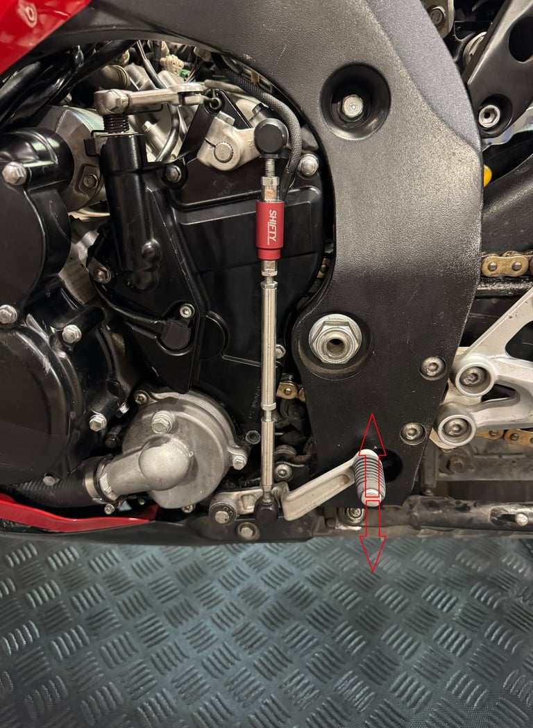
Sensor installation
1. Removing the Standard Linkage
Begin by removing the original shift linkage arm, carefully noting the current position of the shift lever for reference during reassembly.
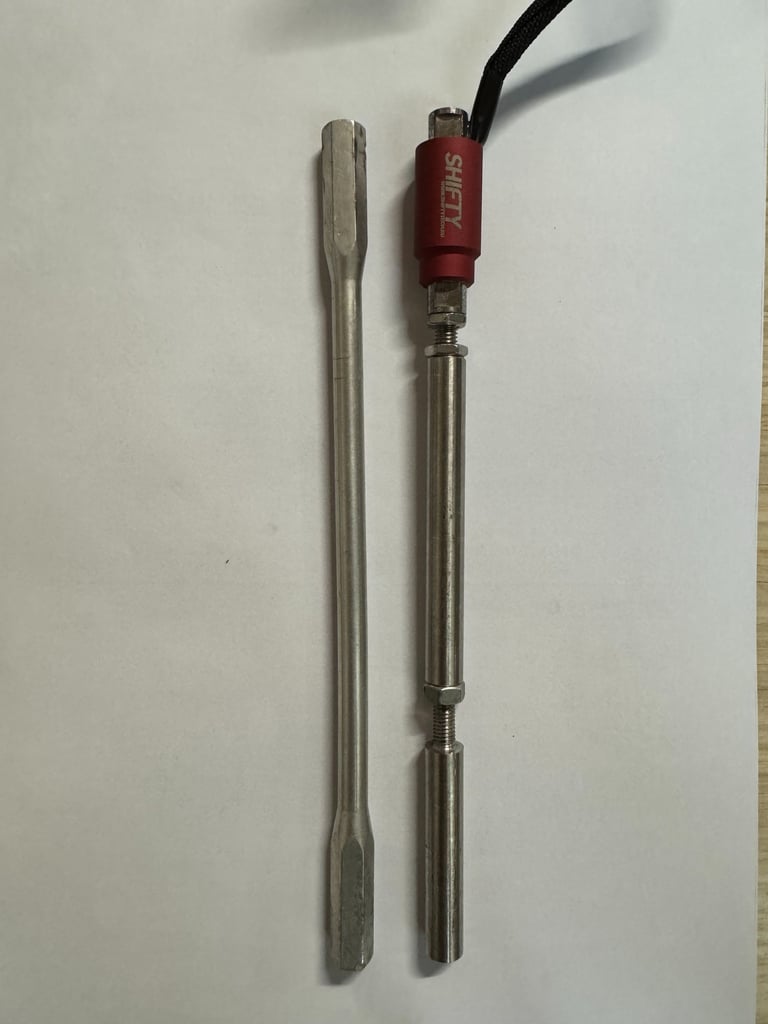
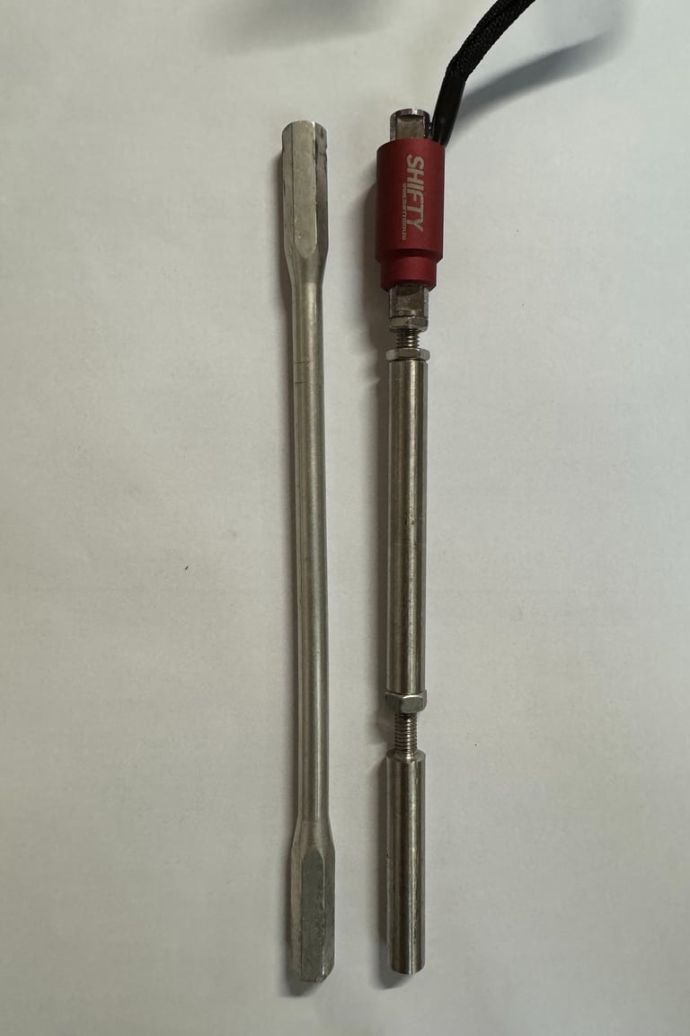
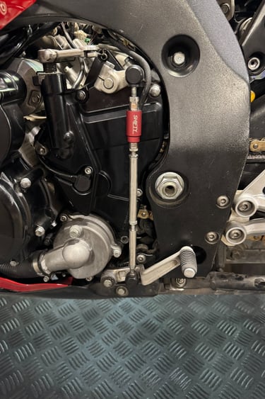
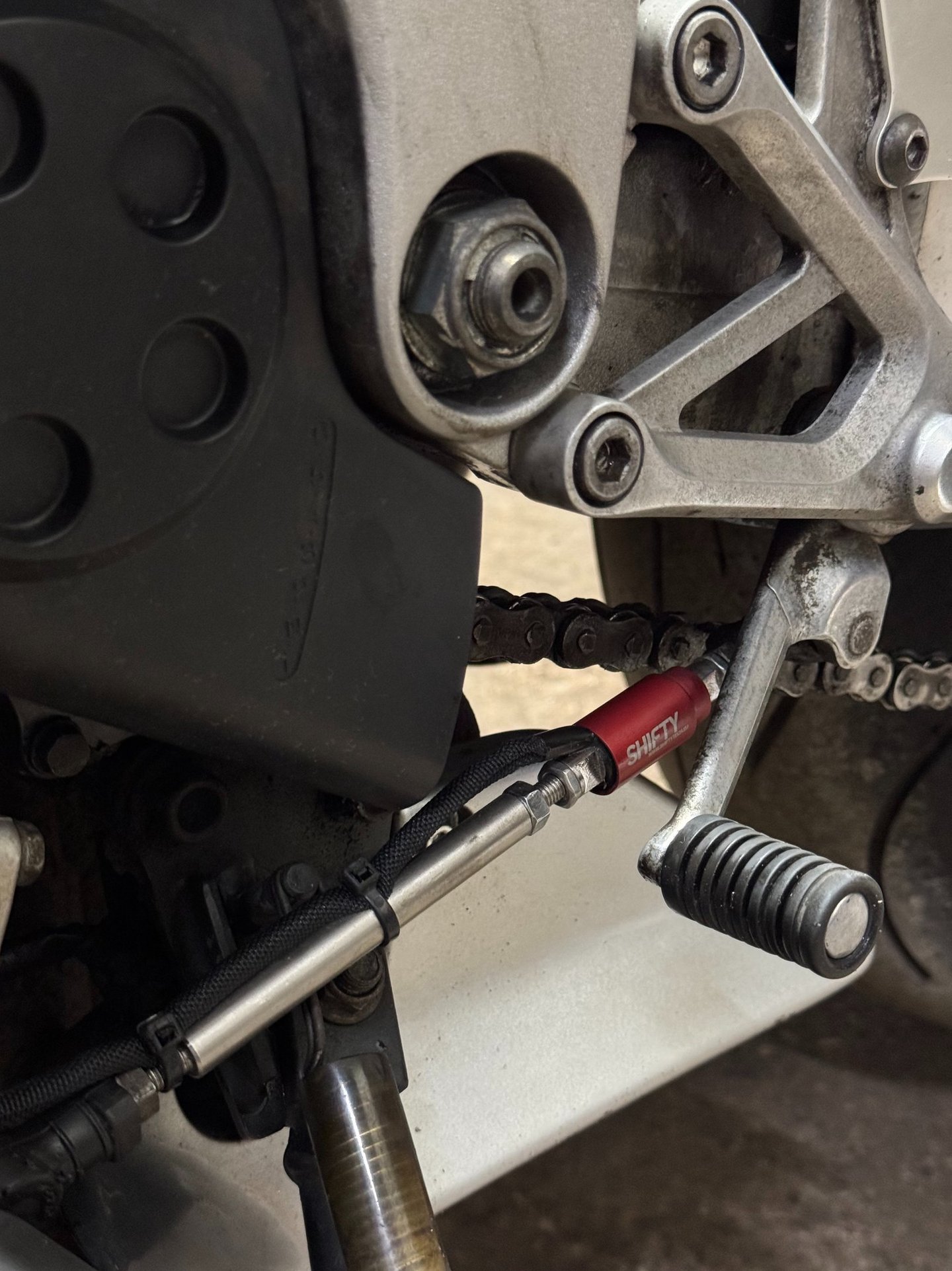
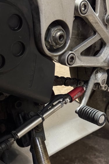
2. Assembling the Sensor and Linkage
Connect the Sensor to the linkage Rod (not included) to replicate the original linkage length. This ensures proper shifting geometry and performance.
Key Installation Considerations:
• Free Movement: The sensor and shift rod must pivot freely at the rose joints. A slight rotational movement should be possible, ensuring there is no binding.
• No Contact or Obstruction: Cycle the shift lever through its full range of motion to confirm the sensor and rod do not make contact with any part of the motorcycle or strain the sensor cable.
• Cable Protection: Avoid overtightening cable ties and do not apply excessive force to the cable between the sensor and the control box. Improper routing or excessive tension can lead to cable damage.
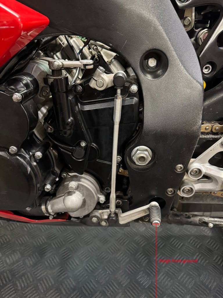
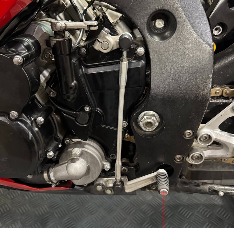
3. Reinstalling the Linkage Assembly
Reinstall the assembled linkage, ensuring the Sensor and its connected cable are positioned so they do not interfere with the shiftlever or any surrounding mechanical components. For optimal performance and signal accuracy, position the sensor as close tothe gearbox as possible. If it's possible, maintain the 90 degrees between the gear levers and linkage rod. In some cases it's not possible to mount the sensor near the gearbox shaft, so other case where sensor is mounted near the shift lever is completely fine.

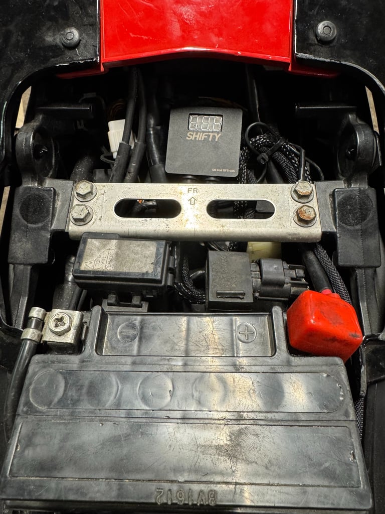
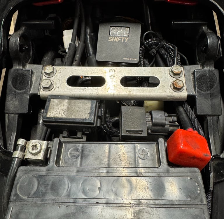
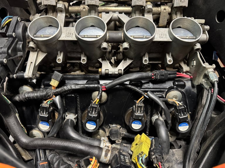
Installing the control box
Locate a secure and protected area on the motorcycle for mounting the control box — ideally under the seat or within a similarly sheltered location. Carefully route all wiring from the control box to the linkage, ensuring cables are free from sharp edges, heat sources, or any moving components that could cause damage. Shifty quickshifter connects directly to the plug-top ignition coils, offering several key advantages. One of the most significant benefits is complete independence from the motorcycle's ECU and factory wiring harness. This design ensures more consistent and precise shifting performance—often surpassing that of ECU-integrated systems.
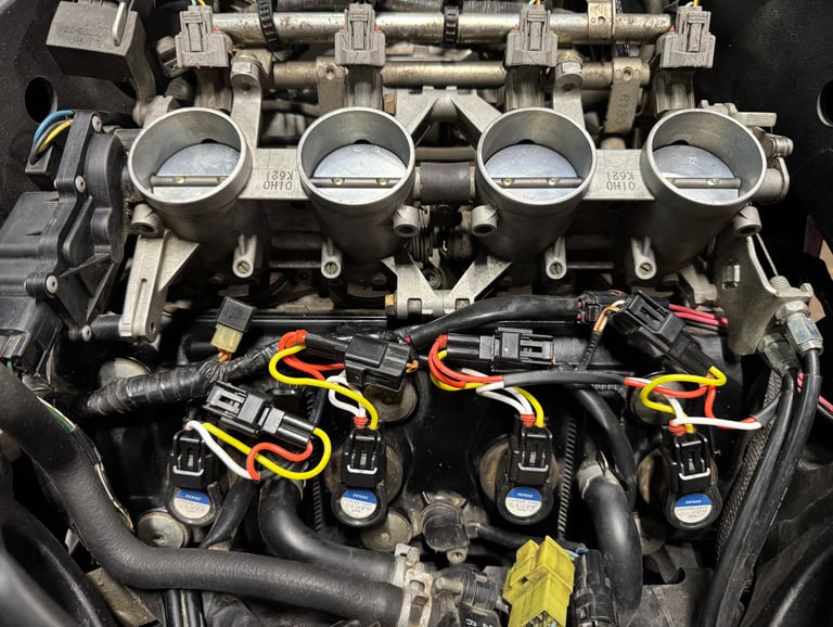
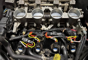
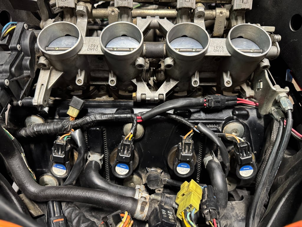
Wiring instructions
The included wiring loom is designed for straight forward installation. Make access to the ignition coils (usually it's needed to remove the fuel tank and air filter box). Simply connect provided wiring loom in-line with the ignition coils. Additionally, attach the ground strap to a clean, reliable chassis ground point.
Note: Do not connect the ground strap to the valve (cam) cover, as this is not a suitable grounding location.
System configuration
The Shifty quickshifter is already pre-configured for your specific motorcycle model and can be used straight forward. However, you can easily fine-tune it to match your own riding preferences using the built-in LED interface.
The following settings can be adjusted:
1. Sensitivity – How much force is needed to trigger a shift
2. Kill Time – The duration the ignition is cut during a shift
3. Shift Direction – COMPRESSION (push) or TENSION (pull)
1. To enter Setup Mode:
• Turn off the motorcycle completely.
• Place the motorcycle on a stand and fold up the side stand.
• Turn on the ignition, but do not start the engine.
• Press and hold the shift lever in either direction for 6 seconds.
• When holding the LED indicators will start countdown, after the countdown the first parameter will appear.
2. Adjusting Settings:
Once in Setup Mode, the settings will appear in the following order:
Sensitivity
• Use the shift lever: push one way to increase, the other to decrease.
• To save and move to the next setting, press and hold the shift lever in either direction for about 3 seconds.
• The LEDs will scroll across to indicate confirmation.
Kill Time
• Adjust using the same method as above.
• Confirm by holding the shift lever for ~3 seconds.
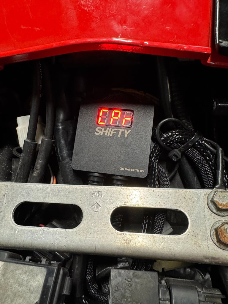
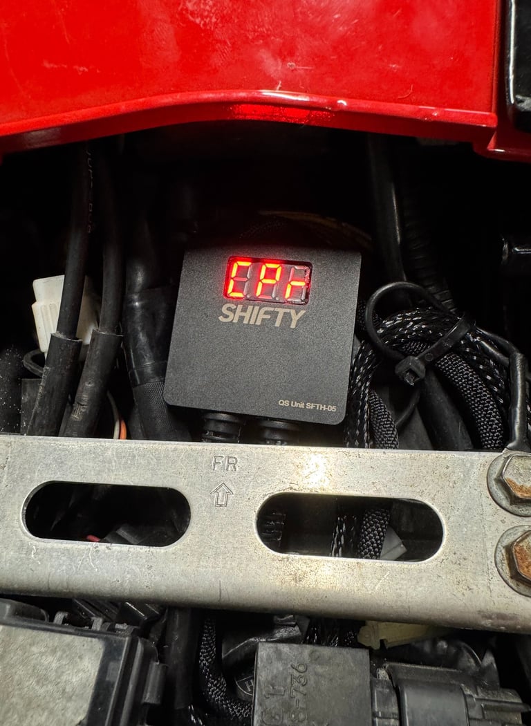
Shift Direction (Push or Pull)
• Choose the correct direction that matches your gear lever setup, LED indicators will display:
• CPR – COMPRESSION
• TNS - TENSION
Confirm the selection by holding the shift lever for ~3 seconds.
3. Final Step
After confirming the last setting, the quickshifter will automatically exit Setup Mode and is ready to use with the new parameters.

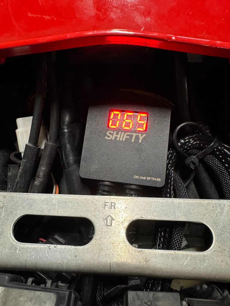
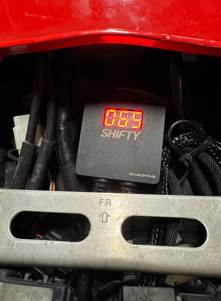

Stationary function test
After installation, it is recommended to perform a stationary test to verify correct sensor operation and configuration. This test is divided into two parts:
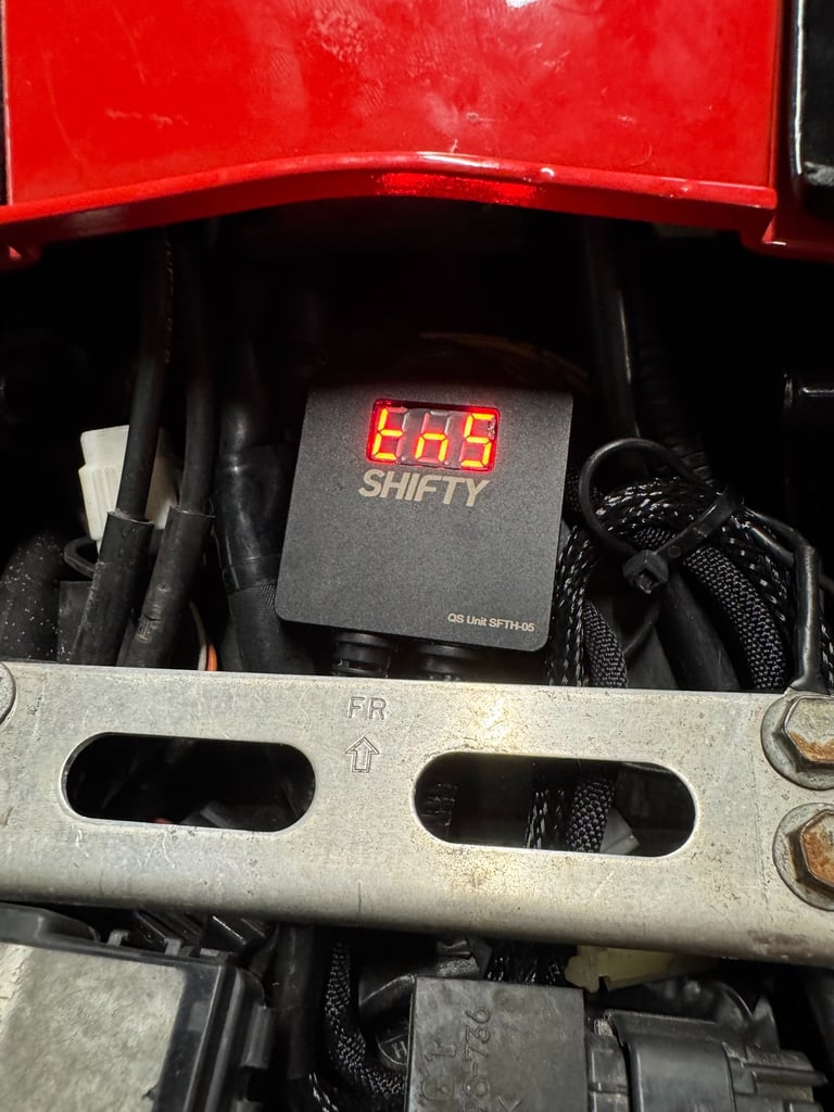
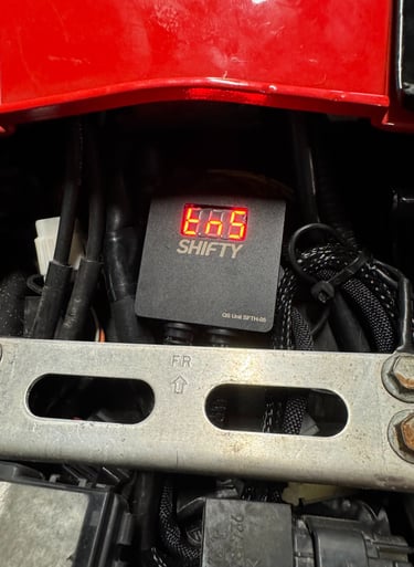
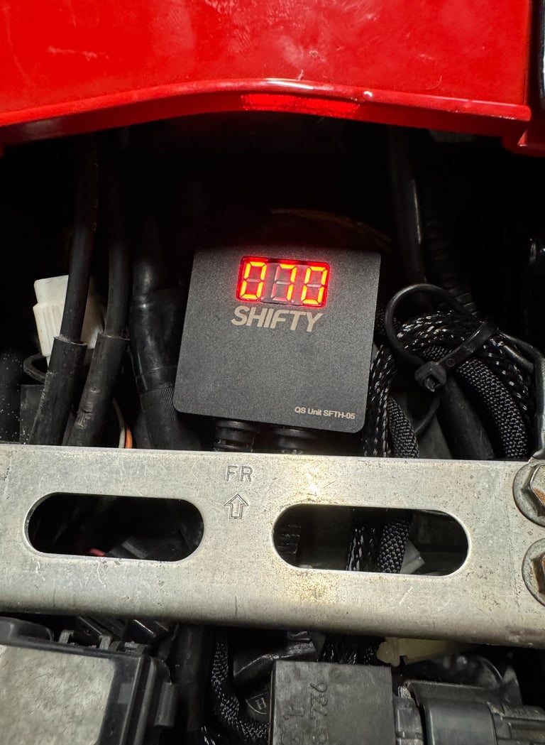
1. LED Sensitivity Check
1. Turn on the ignition to power up the LED display. Do not start the engine.
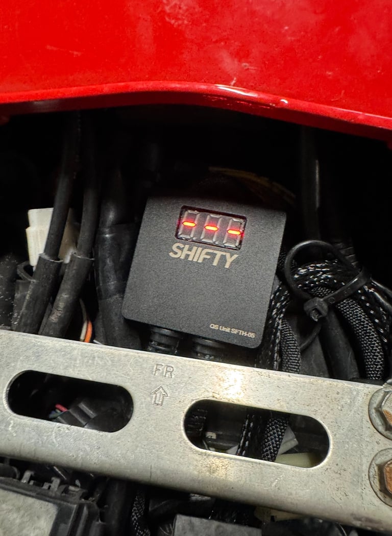
2. While observing the LED indicators, gently press the shift lever in the direction used to shift up/down to the next gear.
3. The LED should briefly flash the lines indicating sensor activation.
4. Ideal sensitivity is achieved when the force required to trigger “SHIFT” is slightly greater than the force needed to engage the next gear.
5. If flashing the lines does not appear, increase the sensitivity setting temporarily for this test.
6. Ensure that the shift direction settings (Compression and Tension) are configured correctly for your setup.
2. Operational Use
Once installation and testing are complete, the Shifty quickshifter is ready for operation. After the clutch has been fully released in 1st gear, the clutch becomes optional for all upshifts.
Usage Tips:
• Use a firm and deliberate motion when pressing the shift lever to achieve the best performance.
• Lower sensitivity settings often result in smoother, more precise shifts.
• The system is designed to initiate an ignition cut once per shift. The shift lever must be returned to its neutral position before the next upshift can be registered.
Important:
Using an incorrect wiring loom or incorrect installation may cause serious damage to you or motorcycle. Such damage is not covered under warranty. Always verify compatibility before proceeding with installation.

USEfull links
Information
© Shiftytech, 2025. All rights reserved.
Returns & REFUNDS POLICY